Wednesday, December 29, 2010

Shaping the panel

Click any picture for a larger view


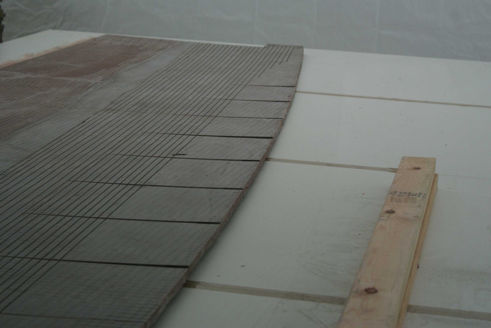
The next big step is to pull the shape into the panel. It is hard to believe we are starting with a flat panel and will end up with a "half hull" shape in just a few steps. We have our flat panel on the table, deck edge radius molded in, glass and gel coat on the outside of the panel and glass and foam on the inside of the panel. Ready for the next step.


Here are the forms we will be using. They are made out of 3/4 inch material, lumber or cut pieces of chip board cut to 4 inch wide strips, some eye bolts and wing nuts and our patterns. The pattern shape is provided by Derek and you just have to cut them out. There is a diagonal support in the framing that will be used to hold the panel at the right angle.


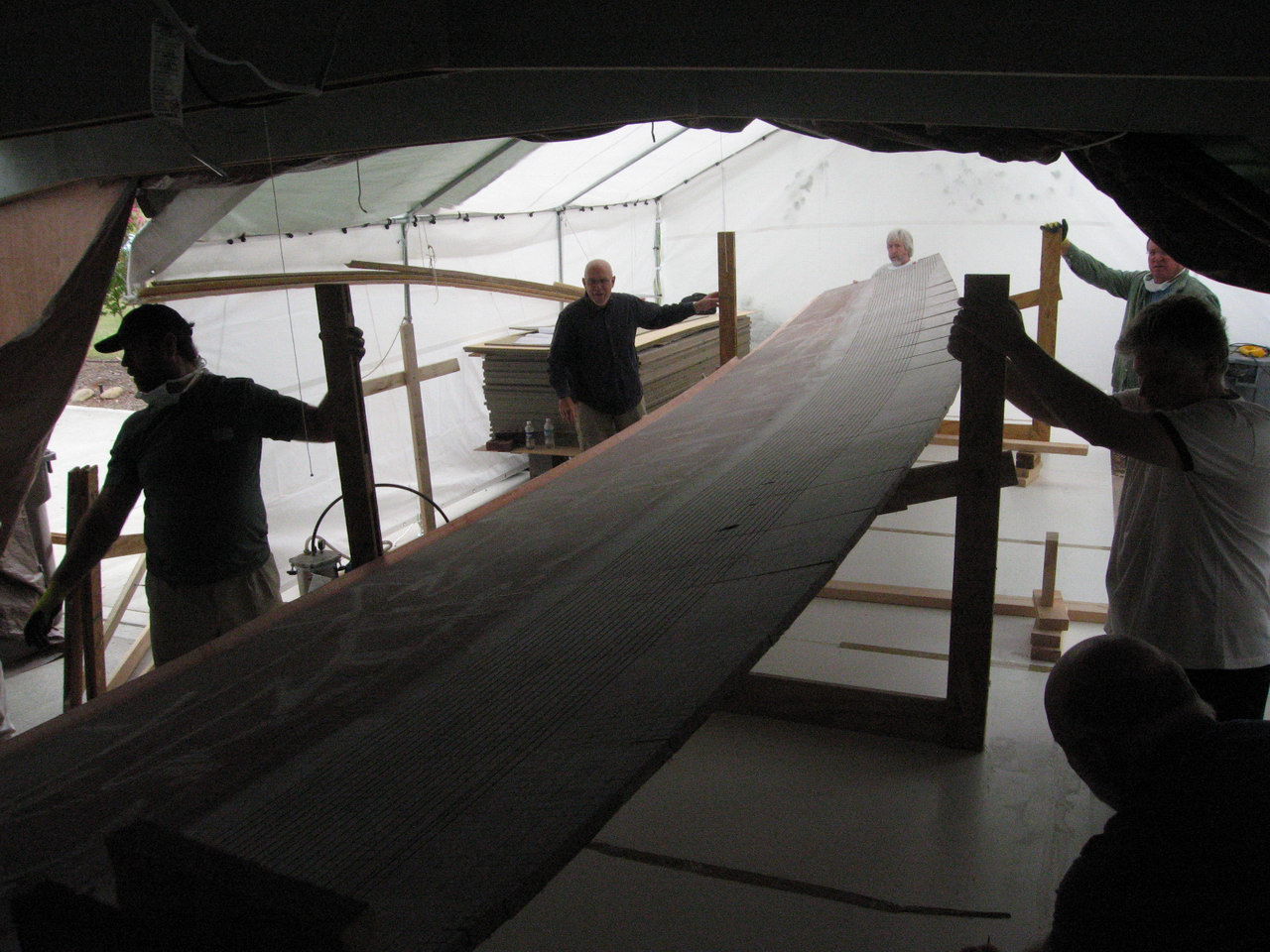
You will probably need some help here. We have to raise the panel up and install it in the frames. The panel is not heavy but it is wiggly and you do not want to bend it or break the deck edge radius or the dart cuts.


All the frames are numbered to correspond to the positions marked on the panel. Once you get a couple of frames up to hold the panel, you can take some time to align everything.


It helps to have feet on the frames so they stand up by themselves.


This is the time to do all the little adjustments. 


We now have all the frames in place and all the adjustments for shape are complete.


Here is a view of the frames from the bow. You may notice that the diagonal support is not at the same height in all frames. It is lowest in the middle of the panel and highest at the bow of the panel. This gives us the fore and aft shape of the hull.


Derek is now attaching the straps to the frames. Notice the strap starts at the bottom of the frame at the shear line of the hull and goes around the panel and back to the top of the frame. We want the pulling force to be applied to the top of the panel as it sits in the frames. The ratchet is at the top of the frame where it will be easy to operate and provide this top bending force. Notice the full length batten is in use again. The batten in this position distributes the bending force on all sections  of the lower hull and contributes to a fair curve.


The straps hook through the eye bolts in the upper and lower corner of the frame.


As you can imagine, there is a considerable amount of force applied to accomplish the forming of the panel. The deck edge radius is next to the frame edge and all this force is applied to it. It is not strong enough to withstand this pressure so to help it survive the strain, we screw it to the frame work close to the foam. Two screws applied here on each frame will prevent the deck edge radius from being broken or deformed.


All the straps are in place, all the adjustments made, so let's get on with it.


Start at station 0. Take up the slack in the straps and then take a couple of clicks. Go to station 1 and do the same. Do this all the way to the stern. Go back to the front and take a couple more clicks in the strap. Work you way down to the stern, taking the same number of clicks at each station. By doing this in a regulated manner, no sudden pressures are applied on any part of the panel and you develop a fair curve as the hull bends into position.

You will notice that you are bending the hull to come up snug to the pattern that is attached to the frame. The bottom end of the pattern starts the bend in the panel and you pull the panel all the way to the top of the pattern.


You can see the outside of the panel taking shape. Notice the gel coat, nice and smooth. No long drawn out fairing needed here. How many hours will this save you?


But wait! Something is not right. Things are creaking and making noise. It sounds like two things are trying to fit in the same space. Derek says to look at the darts. As the panel takes shape, the full length batten allows the pieces between the dart cuts to move as they slide into shape. As two of them come together, there is not enough room for them to move so we must open up the darts a bit more. You do not want to open them too much as this is an area that will have to be filled later. A little jig saw work is all that is required.


The panel is now pulled into position. You can see that the pattern has shaped the bend into a fair curve all along the hull bottom. The hull is touching the pattern at the top and bottom and alone the sides nice and snug.


But what is this? the foam is not even on the inside. There are dart cuts between the frames and patterns and the pressure is not applied exactly even all along the panel. To eliminate this unevenness, we will have to shim up the outside of the panel. This is easily done with bits of wood placed between the straps on the outside of the curve until all the foam is even on the inside.


Well, that just about does it. We have one more step to do and that is glass the inside of the hull.


Prepare for forming the panel

Click any picture for a larger view


We have to clean up the panel in preperation of forming the bottom of the panel. There are lots of little bits of resin left on the panel from the bag removal.


It was decided to remove the small bit of resin that had been deposited on the lower section of the panel. This is the area that will be formed to make the bottom of the hull. A random orbital sander makes short work of this and does not damage the foam.


This closeup shows how the resin penetrates between two sheets of foam. You can see the resin goes right to the bottom of the foam and meets up with the resin that fills the glass on the outside of the panel.


The panel is now clean and all the excess resin on the lower part of the panel has been removed.


We have to cut the foam to allow the required shape to take place. A series of cuts are done from stem to stern with a skill saw. We are removing a kerf the thickness of the saw blade. Derek would like to see a "V" shaped kerf as it makes it easier to fill later and allows more space for the panel to bend. If you know you are going to do this, you might be able to purchase a "V" shaped blade or possibly make one. As we did not have one or have the time to make one, a standard blade was used.


The cut lines were drawn between the upper and lower tangent lines previously marked on the panel. They are approximately 1 inch apart and run the complete length of the panel. They penetrate about half way through the foam.

We are again using the full length batten to cut the kerfs. Lots of weights and help needed here.


We had an interesting thing happen right at the start of this operation. You will notice the wavy line in the first kerf made, on the right side of the picture. Steve had a normal wood cutting blade in the saw and when he started to cut the kerf, the blade heated up and distorted and caused the saw to wonder all over the place. This would not do so what was wrong? Interestingly, I had the same experience cutting scarfs in a long piece of plywood. One of the guys suggested getting a carbide blade with sufficient cooling holes in the blade to prevent this happening again. A good quality saw blade was purchased, with the cooling holes spaced around the blade and it cut nice straight lines.


The kerfs are cut about half way through the foam. This is the stern view.


Here they run off the panel at the stem.


Now we come to the second set of cuts to be made. These cuts are called "darts" and are cut right through the panel, including the glass on the outside of the panel. When you pull the form into the panel, there is rocker formed in the bottom. This means the panel shape must rise to the bow and well as the stern. Cutting the darts removes enough material for the rocker to be placed in the panel.  The darts are marked on the panel from the template information. Careful not to cut the table underneath the panel!


We were going to cut the darts with the skill saw but the kerf was way too large. The rest of this dart and the others were cut with the jig saw.


OK, the panel has all the cuts necessary to pull the shape into it. It looks like it is already trying to take the shape we want as the edge is lifting off the table.


Even with the straight sided kerfs in the foam, the panel bends with a nice fair curve.


Friday, December 24, 2010

Start the Resin

Click on any picture for a larger view


The resin is starting to flow over the panel. We have only one hose open at this time. You can see the resin flowing out from both sides of the number one hose. We opened this hose first as the resin has the longest distance to travel from this hose to the deck edge radius. 

Steve mixed small batches of resin and brought them to the reservoir as the previous batch was used up. If you mix large batches of resin, they have a tendency to kick faster if there is a large volume in the reservoir. We want as much time as we can get with a panel this size. 

Do not allow the reservoir to be empty as this will allow air into your system and will effect the resin flow. We are infusing this panel in the evening and the temperature was cool so we thought we would have ample working time before the resin gelled. You can see by the watch in the corner, we are into the infusion just over 9 minutes.


You can see the resin working its way along the scoring on top of the foam. 


There were a few times during this process that we had to help the resin flow. We found that if you pulled up on the bag a bit, it would create a channel and that would help the resin flow to areas that we felt were not getting enough resin, fast enough.


Here is the panel, over 30 minutes into the infusion process. Looking good. With close inspection, there does not seem to be any area of the panel that is not covered with resin. 


If you look carefully, you can see the resin has already passed the deck edge radius and on its way to the vacuum lines that circle the panel.


View from the stern of the panel.


We are at 30 minutes, 58 seconds and it looks like the whole panel is finished. You can see the resin has gone past the edge of the foam and is making its way to the vacuum lines. We did not have any resin get into the lines and they could be used again. Any hose or material that the resin comes into contact with will be unusable as the resin cures and can not be removed. 


We left the panel over night. We wrapped it in tarps and blankets. The next morning we removed the bag and all the hoses, etc. This is one reason for the peel ply. It allows easy removal of the bag, shade cloth and hoses. 


A Look At Some of the Equipment

Click on any picture for a larger view


First item we see here is the vacuum pump set up. We have the pump with a vacuum gauge on top, connected to a paint pot used as a resin catcher to protect the pump. You have to make sure the resin never reaches the pump. If it does, you will have to buy a new pump. Any resin that gets though the panel and comes towards the pump, will be caught in the paint pot. The preventative measures placed on the panel worked very well and we never had any resin even get into the vacuum hose running from the table to the paint pot. The whole affair is mounted on a little trolley on wheels so it can be moved around with ease. The black plastic hose is the hose coming from the table.


Next we have the resin reservoir. You can see the resin input lines that go right to the bottom of the bucket. Make sure you do not allow air into these lines once you start your infusion process. The hoses are attached to the sides of the bucket with wire to make sure they do not move off the bottom once the process starts. You will want to cut the hoses at an angle to allow resin to enter the hoses from the bottom of the bucket. We are using "Vice Grips" as valves for the the resin. This will allow us to open or close any hose as the infusion goes on.


We now have the full vacuum applied and the bag is down tight. We do have leaks and are trying to find them now. If the leaks are too severe, you will jeopardize the infusion and you might end up with a dry spot on the panel. We see our resin reservoir and feed lines going to our three distribution hoses.


We are ready to roll. Larisa is holding the reservoir up off the floor. You need the reservoir to be as close to the level of the table as possible to assist in the drawing out of the resin. You can see two areas where we were trying to solve leak problems. The areas are enclosed with the yellow sticky tape. We figured the leaks could have been caused by a problem joint in the table and that would let air into the bag from the bottom. Even with the leaks, we managed to pull 17 on the gauge. Steve had managed 25 previously on some other items they made on this table but Derek felt we could go with 17. So, off we went.


Monday, December 20, 2010

The vacuum bag goes on

Click on any picture for a larger view

The bag must be one continuous piece of plastic material. There can be no joints or seams in the bag as this will be opportunities for leaks. The bag is considerably larger then the panel so we can make sure pressure will be applied evenly across the whole assembly.


We remove the top backing on the black double sided tape that has been placed on the table surface surrounding the panel. The bag will be attached here. You will notice a bunch of yellow pieces of tape along the edges of the bag. These are pleats that are made to accommodate the oversize of the bagging material and to make sure there are no constricted areas when the vacuum is applied.

You also see a black plastic hose held to the table with a clamp. This hose leads to our vacuum pump and is attached to a perimeter spiral wrap hose that allows air from under the bag to be drawn into the vacuum pump. This spiral wrap hose is inside a fold of the peel ply. We want to avoid resin being drawn into the vacuum hose as much as possible. 


Here you can see the black double sided tape goes around the whole panel. Lots of pleats held together with yellow double sided tape and as you can see, the bag is very much larger then the panel. This extra bag material makes sure there are no stressed areas once the vacuum is applied. Stressed areas might allow the panel assembly to shift or may impede the flow of resin when infusing.


Here you can see the whole panel under the bag material. Again, lots of pleats to allow good vacuum and resin flow.


Now the fun starts. Apply some vacuum and check for leaks. On this panel, we had some leaks, possibly from the table joints, not sure but we chased these leaks for two hours until we decided that we had enough vacuum to allow the resin to infuse so lets get at it. You can see the bag is pulled down a bit, not entirely flat yet but getting there. Steve had an acoustic leak checker and although we spotted some leaks quickly, it was another matter to get them to stop.


Wednesday, December 15, 2010

Apply the vacuum bag

Click any picture for a larger view

Before the vacuum bag can be applied, there are a number of things that must be added to the assembly. One item we must make are the resin infusion lines that will allow the resin to spread out over the whole panel. These lines are made out of 1/2 inch ID black plastic water hose available at any hardware store. We drilled 1/8 inch holes right through the plastic hose every 6 inches. You will have to remove any bits of plastic that hang on to the hose after the holes are drilled as they might puncture the bag when the vacuum is applied. To help disperse the resin, the hose is then inserted into a shade cloth cover that runs the whole length of the hose. These covers were made up before hand. 


The line is covered with shade cloth. This cloth has very open pores that will allow the resin to flow with out restrictions. This material is sometimes called "bleeder cloth" because it allows the air inside the bag to move freely to the evacuation lines. 


Here is the first resin line being cut for length. You will also see a line on the outside of the panel, about 1 foot from the edge of the table. This is a length of double sided tape that runs completely around the panel. The bag will attach to this tape and there must be no leaks between joins in this tape. The top cover is still on the tape and will be removed only when it is time to place the bag on the panel.


Next we cover the panel with a layer of peel ply. This material is placed directly on top of the last layer of glass and before any resin lines or shade cloth. When the panel has been infused and cured, the peel ply will make it possible to remove the resin lines, bag, and shade cloth from the panel. Larisa is attaching some shade cloth to the deck edge radius former to ensure good resin penetration and coverage 


Now Steve is attaching the first resin line to the panel. 


Now we attach the second resin line.


And the third and final line goes on.