Friday, December 24, 2010

Start the Resin

Click on any picture for a larger view


The resin is starting to flow over the panel. We have only one hose open at this time. You can see the resin flowing out from both sides of the number one hose. We opened this hose first as the resin has the longest distance to travel from this hose to the deck edge radius. 

Steve mixed small batches of resin and brought them to the reservoir as the previous batch was used up. If you mix large batches of resin, they have a tendency to kick faster if there is a large volume in the reservoir. We want as much time as we can get with a panel this size. 

Do not allow the reservoir to be empty as this will allow air into your system and will effect the resin flow. We are infusing this panel in the evening and the temperature was cool so we thought we would have ample working time before the resin gelled. You can see by the watch in the corner, we are into the infusion just over 9 minutes.


You can see the resin working its way along the scoring on top of the foam. 


There were a few times during this process that we had to help the resin flow. We found that if you pulled up on the bag a bit, it would create a channel and that would help the resin flow to areas that we felt were not getting enough resin, fast enough.


Here is the panel, over 30 minutes into the infusion process. Looking good. With close inspection, there does not seem to be any area of the panel that is not covered with resin. 


If you look carefully, you can see the resin has already passed the deck edge radius and on its way to the vacuum lines that circle the panel.


View from the stern of the panel.


We are at 30 minutes, 58 seconds and it looks like the whole panel is finished. You can see the resin has gone past the edge of the foam and is making its way to the vacuum lines. We did not have any resin get into the lines and they could be used again. Any hose or material that the resin comes into contact with will be unusable as the resin cures and can not be removed. 


We left the panel over night. We wrapped it in tarps and blankets. The next morning we removed the bag and all the hoses, etc. This is one reason for the peel ply. It allows easy removal of the bag, shade cloth and hoses. 


A Look At Some of the Equipment

Click on any picture for a larger view


First item we see here is the vacuum pump set up. We have the pump with a vacuum gauge on top, connected to a paint pot used as a resin catcher to protect the pump. You have to make sure the resin never reaches the pump. If it does, you will have to buy a new pump. Any resin that gets though the panel and comes towards the pump, will be caught in the paint pot. The preventative measures placed on the panel worked very well and we never had any resin even get into the vacuum hose running from the table to the paint pot. The whole affair is mounted on a little trolley on wheels so it can be moved around with ease. The black plastic hose is the hose coming from the table.


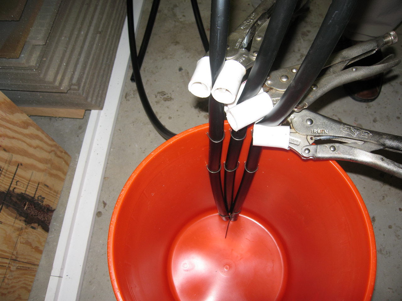
Next we have the resin reservoir. You can see the resin input lines that go right to the bottom of the bucket. Make sure you do not allow air into these lines once you start your infusion process. The hoses are attached to the sides of the bucket with wire to make sure they do not move off the bottom once the process starts. You will want to cut the hoses at an angle to allow resin to enter the hoses from the bottom of the bucket. We are using "Vice Grips" as valves for the the resin. This will allow us to open or close any hose as the infusion goes on.


We now have the full vacuum applied and the bag is down tight. We do have leaks and are trying to find them now. If the leaks are too severe, you will jeopardize the infusion and you might end up with a dry spot on the panel. We see our resin reservoir and feed lines going to our three distribution hoses.


We are ready to roll. Larisa is holding the reservoir up off the floor. You need the reservoir to be as close to the level of the table as possible to assist in the drawing out of the resin. You can see two areas where we were trying to solve leak problems. The areas are enclosed with the yellow sticky tape. We figured the leaks could have been caused by a problem joint in the table and that would let air into the bag from the bottom. Even with the leaks, we managed to pull 17 on the gauge. Steve had managed 25 previously on some other items they made on this table but Derek felt we could go with 17. So, off we went.


Monday, December 20, 2010

The vacuum bag goes on

Click on any picture for a larger view

The bag must be one continuous piece of plastic material. There can be no joints or seams in the bag as this will be opportunities for leaks. The bag is considerably larger then the panel so we can make sure pressure will be applied evenly across the whole assembly.


We remove the top backing on the black double sided tape that has been placed on the table surface surrounding the panel. The bag will be attached here. You will notice a bunch of yellow pieces of tape along the edges of the bag. These are pleats that are made to accommodate the oversize of the bagging material and to make sure there are no constricted areas when the vacuum is applied.

You also see a black plastic hose held to the table with a clamp. This hose leads to our vacuum pump and is attached to a perimeter spiral wrap hose that allows air from under the bag to be drawn into the vacuum pump. This spiral wrap hose is inside a fold of the peel ply. We want to avoid resin being drawn into the vacuum hose as much as possible. 


Here you can see the black double sided tape goes around the whole panel. Lots of pleats held together with yellow double sided tape and as you can see, the bag is very much larger then the panel. This extra bag material makes sure there are no stressed areas once the vacuum is applied. Stressed areas might allow the panel assembly to shift or may impede the flow of resin when infusing.


Here you can see the whole panel under the bag material. Again, lots of pleats to allow good vacuum and resin flow.


Now the fun starts. Apply some vacuum and check for leaks. On this panel, we had some leaks, possibly from the table joints, not sure but we chased these leaks for two hours until we decided that we had enough vacuum to allow the resin to infuse so lets get at it. You can see the bag is pulled down a bit, not entirely flat yet but getting there. Steve had an acoustic leak checker and although we spotted some leaks quickly, it was another matter to get them to stop.


Wednesday, December 15, 2010

Apply the vacuum bag

Click any picture for a larger view

Before the vacuum bag can be applied, there are a number of things that must be added to the assembly. One item we must make are the resin infusion lines that will allow the resin to spread out over the whole panel. These lines are made out of 1/2 inch ID black plastic water hose available at any hardware store. We drilled 1/8 inch holes right through the plastic hose every 6 inches. You will have to remove any bits of plastic that hang on to the hose after the holes are drilled as they might puncture the bag when the vacuum is applied. To help disperse the resin, the hose is then inserted into a shade cloth cover that runs the whole length of the hose. These covers were made up before hand. 


The line is covered with shade cloth. This cloth has very open pores that will allow the resin to flow with out restrictions. This material is sometimes called "bleeder cloth" because it allows the air inside the bag to move freely to the evacuation lines. 


Here is the first resin line being cut for length. You will also see a line on the outside of the panel, about 1 foot from the edge of the table. This is a length of double sided tape that runs completely around the panel. The bag will attach to this tape and there must be no leaks between joins in this tape. The top cover is still on the tape and will be removed only when it is time to place the bag on the panel.


Next we cover the panel with a layer of peel ply. This material is placed directly on top of the last layer of glass and before any resin lines or shade cloth. When the panel has been infused and cured, the peel ply will make it possible to remove the resin lines, bag, and shade cloth from the panel. Larisa is attaching some shade cloth to the deck edge radius former to ensure good resin penetration and coverage 


Now Steve is attaching the first resin line to the panel. 


Now we attach the second resin line.


And the third and final line goes on.


Tuesday, December 14, 2010

Inside layers of glass

Click on any picture for a larger view

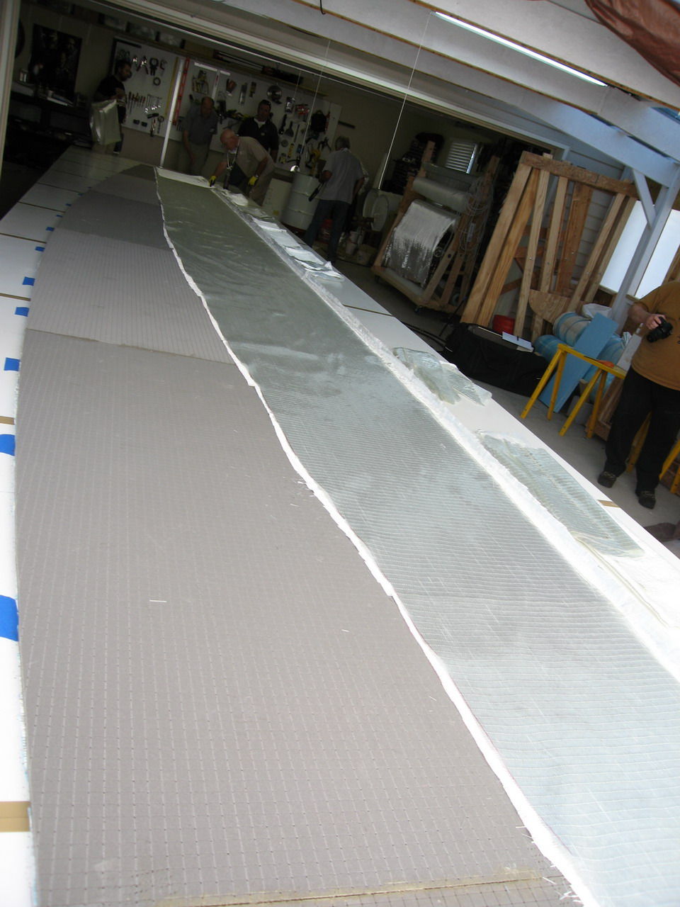
We now place two layers of 10 oz. unidirectional glass, 90 degrees to each other like we did on the outside of the panel. We do not cover the whole panel with glass on the inside as the lower portion, the keel area, is formed later to make a fair round bottom on the hull. This first layer has the strands running from the deck edge radius former towards the keel area as far as the line we saw Steve make on the foam.


Our second layer runs from the stem to the stern and is trimmed to the same line as the other layer.


Here we are. Gel coat on the bottom, two layers of glass, one layer of foam, and the final two layers of glass. Now it is time to bag this puppy.


One of the great things about this method of hull building is you can take as much time as you like. We had a bunch of people working on this panel and got it put together is short order, but if you were working alone, it will take longer. It does not matter. There are no time constraints until you let the resin into the panel. You can fix mistakes, make changes, reassemble the whole panel, there is no pressure.

Placing the foam sheets

Click any picture for a larger view

Here we see the foam laid out on the table with the template on top for marking the foam for cutting. The individual foam pieces are held together with a building product, sometimes called “Gang Plates”. These are steel plates, about 2 inches wide and 4 inches long with lots of sharpened legs formed through them and you drive them into the foam at the junction points to hold the individual panels together. Available at any building store. You do not have to worry about any holes the legs make in the foam as they will be filled with resin during the infusion. Another good idea is to make wiggly lines between each junction so that when you reassemble the panel, all the individual pieces go together in the right places.

The material being used for this project is Divinycell PVC foam, 5/8 inch thick, 80 pound density, cross cut on one side and drilled through. The cross scoring and through drilling helps the resin travel over the foam and through to the other side during the resin infusion process. A good information site with specifications and uses is http://www.diabgroup.com/europe/products/e_prods_2.html This is one manufacturer of foam products. There are others.


A closer look at the “Gang Plates”.


Steve is marking the foam with a line that shows the lower extent of the glass on the inside of the panel. The lower portion of the panel will be formed and therefore does not require glass at this time. This is the first time we see the use of the full length batten. This batten is used to mark fair lines on the panel.


For the foam to fit flat on the glass and the table, we have to cut the rebates into one side of the foam, for the bow and the stern.


All we have to do now is remove the “Gang Plates” and we are ready to put down the inner glass layers. The single line on the panel is the lower limit of glass for the inside of the panel.


Just before we install the upper layers of glass, you can see that the top of the foam close to the deck edge radius former is chamfered. This is to help the glass make a fair transition from the surface of the foam , down into and around the deck edge radius former. Glass does not like abrupt changes and the chamfer helps a lot. 


Sunday, December 12, 2010

Outside layers of glass

Click any picture for a larger view

We are ready to put down the first layer of glass. We are using 10 oz. unidirectional glass, two layers on the outside, placed 90 degrees to each other. One advantage of this glass choice, you can buy a larger amount of a single type to get a better discount.

Here is all the glass for the first layer, cut and laid out on the table. The first layer, or outside layer, the strands of glass will be orientated from the deck edge radius to the keel


The individual pieces are laid out and trimmed to fit. You want the glass to cover the whole inside of the deck edge radius former and then trim to the edge. A light spray adhesive makes the job a bit easier as it all wants to slide around a bit. With the spray adhesive, you can keep the glass inside the former and trim to fit.The bottom edge is trimmed to the dotted blue line which is the lower edge of the panel.


The first layer is going down very nicely.


The first layer is complete. The glass extends over the stern rebate template. This is the full size of the panel.


The view from the bow. The glass also extends over the bow rebate template.


The bow rebate template and the deck edge radius former meet. Here you can see the orientation of the glass strands.


Second layer of glass running bow to stern.


Edge must still be placed in to the deck edge radius former.